Energy efficiency – the order of the day (part 2 of 3)
Reducing energy consumption is a key problem for the brick and tile industry in Europe and, in the long term, worldwide. The significant rise in energy prices over the past few years directly suggests a more economical utilisation. In the future, rising CO2 prices will increase energy prices. In his new book “Optimum drying and firing of bricks”, Dr Stefan Vogt discusses in detail the ways in which energy can currently be saved. This article, which is published in three parts, presents an extract from this.
Further increase in the efficiency of rapid dryers
Bricks are still dried today exclusively in convection dryers, that is by means of air movement. Accordingly, the effectiveness of the air circulation also determines the achievable economic indicators of a dryer, like the thermal energy and the electricity consumption or the necessary installation footprint [50]. The experience shows that dryers with relatively short drying times also consume less energy and installation space and therefore need lower investment and operating costs [39 – 50]. The first rapid dryers were developed in the late 1950s in France and Italy for the horizontally perforated bricks with a high perforation percentage common in these countries [85]. The drying times took between 2 and 5 h. In the 1970s, jet dryers caused a sensation for small-size backing bricks in Germany, the drying times ranging between 40 and 80 minutes [39, 40]. Since the mid-1990s, rapid dryers have become firmly established for clay blocks [41, 42] and since the mid-2000s, solutions have been available for roofing tile rapid dryers [43 – 47]. Rapid dryers were developed with the aim of maximizing efficiency with consideration of general economic conditions.
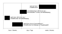
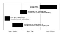
While the drying times for conventional dryers with the use of hot air are in the range of days, rapid dryers generally only need a few hours for drying (»Table 4). Large-size vertically perforated clay blocks can be dried in 1.5 to 2.0 hours and roofing tiles in 2.0 and 5.0 hours. Compared to conventional dryers, the drying times are therefore shortened by 70 to 90 %. The short drying times achieved in rapid dryers can be attributed primarily to significantly improved material and heat transfer conditions at the surface of the bricks. At the same time, because of the directed flow of air onto the bricks, the stresses generated inside the brick during the drying process decrease. Rapid drying therefore ultimately permits gentler drying. The emerging potential is utilized for further reduction of the drying time. The practical experience with rapid dryers also shows that thermal energy and electricity consumption or the necessary installation space are much lower or smaller compared to conventional dryers.
For cost-effective realization of rapid drying, the following conditions must be fulfilled [47 – 49]:
1. Minimization of the shrinkage differences in the brick during the drying process based on participation of all brick surfaces in the material and heat transfer in line with the specific requirements
2. Equal treatment of all bricks in the dryer setting
3. Maximization of the thermal energy utilization based on application of the maximum useful material and heat transfer
4. Minimization of the pressure loss in the circulation system for minimization of the power consumption
Conventional dryers permit hardly any improvements in respect of these four aspects. The large-size vertically perforated clay blocks common in German-speaking countries have a perforation percentage of around 50 %. While in conventional dryers the bricks are predominantly dried starting from the outer surfaces, the key criterion for rapid drying of large-size vertically perforated clay blocks is the extensive inclusion of the inner surfaces of the perforations in the drying process. The ratio of external to internal surface area lies between 1:3 (older models) and 1:8 (vertically perforated clay block with filigree perforation pattern). The inclusion of the inner surface area of the clay block in the drying process therefore opens up great potential for accelerating the drying process. Besides the increased drying surface, at the same time the moisture route inside the brick decreases significantly. Whereas in conventional drying predominantly from the outer surfaces, moisture must be transported several centimetres from the inside of the brick to the surface, in rapid drying with the air flowing through the clay blocks, the moisture route is only a few millimetres from the inner web and outer shell of the block. To achieve stress-minimized drying, the ratio of through-flow (flow through the internal surfaces) to around-flow (flow around the outside surfaces) must be chosen such that during drying the outer shell of a brick shrinks at the same rate as the web inside the brick.
From the above observations, it emerges how air flow can be optimally directed at perforated clay blocks. Conclusions concerning the optimum setting depth result from »Fig. 10. The equal diameter of the perforations in the vertically perforated blocks measure around 1.6 cm. For the common block heights of 24 cm, the relative channel length l/d after flow-through of just one block is already 15. Therefore, at the end of the flow path, the block dries at only the half the rate, similar to the last brick in conventional dryer settings. The conclusions from »Fig. 10 are supported by the practical experience with the rapid dryers built so far, in which the air flows through one to five tiers of clay blocks. While a single tier of clay blocks can be dried in approximately 2 h (»Fig. 11), for every additional block the air flows through, the drying time increases by another 1.5 to 2.5 h (»Fig. 12) [12]. An increase in the drying time generally leads to an increase in the size of the installation area for the dryer and ultimately to increased investment. From these briefly outlined considerations, it can be derived that the through-flow depth in the rapid drying of the vertically perforated blocks with a filigree perforation pattern should be a maximum of one tier of clay blocks.
In the construction of efficient rapid dryers, a number of aspects must be taken into consideration. For a simple design of the loading and unloading machines, a single-tier horizontal arrangement of the dryer setting over the base initially appears ideal. For the realization of simple circulation systems, the clay blocks must preferably lie with their cut surface on the drying support (»Fig. 11). In the built rapid dryers of this type, the shrinkage of the clay blocks is hindered at the support surface such that the blocks can become conical in shape during drying [12].
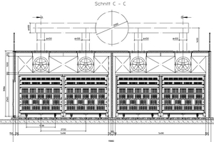
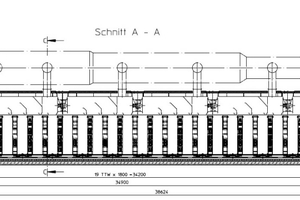
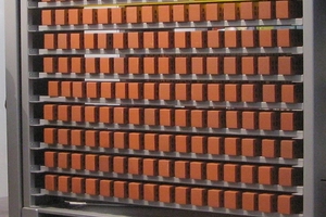
Accordingly, clay blocks are dried lying on their outer shell in most rapid dryers for vertically perforated clay blocks. The blocks are set in several tiers above each other on battens in drying frames arranged lengthways to the direction of movement of the dryer cars. The atmosphere inside the dryer is circulated by means of axial fans arranged at the sides (»Fig. 12). Presumably, to meet the need to save space, almost all plant engineering companies have gone over to dryer systems in which the air flows through at least two tiers of bricks after each other. The drying times are then 4.2 to 5.4 hours and the installation area measures 2.0 m2 per tonne of daily output. Conventional dryers need an installation footprint of 3.0 to 4.4 m2 per tonne daily output. Accordingly, standard rapid dryers already have a 30- to 50-% smaller installation footprint than conventional dryers with rotary fans or slotted walls. The installation footprint can be reduced in size again if the prevalent but spatially unfavourable orientation of the drying frame in the direction of movement of the cars is abandoned, and in addition the drying air only has to flow through one tier of clay blocks. For this the drying frames are arranged crosswise to the direction of travel (»Fig. 13).
The dryer cars must be equipped with flow chicanes in such a way as to enable an efficient flow of air around and into the bricks. Hot air should be supplied as far as possible for each drying frame (»Fig. 14) on the cars by means of axial fans arranged on the ceiling and injection slots in the intermediate ceiling.
Besides large-size vertically perforated clay blocks, clinker bricks can also be dried rapidly (»Fig. 15). In »Table 5, the economic data of continuous dryers with rotary fans or slotted walls for masonry bricks are listed. A comparison reveals hardly any noticeable differences between the two circulation types. That means that none of the competitive systems shows clear economic advantages. In the economic data, the standard rapid dryer as well as the high-efficiency dryer stand out as being positive. Rapid dryers operate particularly efficiently if they use hot-air temperatures above 240 °C (»Table 2, part 1 in ZI 5/2024). Such high hot-air temperatures are not used in all standard rapid dryers, which is why their specific energy consumption can certainly advance to the relatively high values of the conventional dryers. The circulation fans in the high-efficiency dryer only fulfil the functions of mixing in the hot air and homogenization of the flow in the dryer cross-section. The big pressure losses caused by the diversion of a large part of the main flow as in standard rapid dryers (»Fig. 11 and 12) are avoided in this way. The actual flow at the bricks is generated by the supply and exhaust air fans. Accordingly, the specific power consumption in high-efficiency dryers ranges only between 2.5 and 5.0 kWh/t fired ware. Conventional dryers and standard rapid dryers, on the other hand, need 3 to 4-times such levels. The specific thermal energy requirement is around 10 to 20 % lower in the high-efficiency dryer. In addition, the installation footprint is two to three times smaller than for standard rapid dryers and even around five times smaller than for a conventional dryer (»Table 5). The compact design in combination with the use of heat pumps or ambient air drying enables much smaller dryer dimensions that with conventional dry processes.
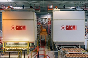
Rapid dryers for roofing tiles were realized in 2005 by Rotho and in 2012 by SACMI at just one location in each case. On account of disadvantages common in conventional dryers caused by the parallel flow of air to several tiles lying one behind another, Rotho performed tests and simulations [44] to investigate other types of flows of air onto a roofing tile. Here, perpendicular flow of air onto the roofing tiles proved the most effective alternative. The perpendicular flow of air onto the roofing tiles by means of impact jets [45 – 48] offers several decisive advantages compared to parallel flow like:
The possibility of even flow of air to the top and bottom sides of the tiles
Avoidance of lee sites and dead flow zones at the tiles
A high heat and material transfer even at low flow velocities
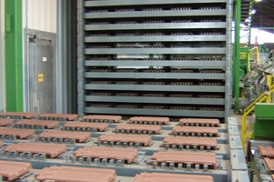
Impact flow is technically realized with perforated plates above and below the tile (»Fig. 17). The tiles are placed on spacers (QuickPoints) (»Fig. 16). With additional variation of the number of the perforations and diameter of the perforations, the partial drying conditions can be adapted to the different parts of the roofing tile such that low-stress drying is possible, largely without drying-related differences in shrinkage. To achieve as fast as possible drying with minimum requirement of circulation power, various perforation diameters, shapes and percentages as well as exit speeds in the nozzle array were tested. From these tests, the following conclusions are derived [45, 46]:
At exit speeds higher than 3.0 m/s, the drying rate of the tiles increases only slightly.
Different perforation shapes (cross shape, quarter and semi-circle shapes) result in hardly measurable differences compared to a simple circular cross-section.
The smaller the perforation percentages in the plate are, the smaller the volume flow needed to achieve a certain drying rate. (for a small perforation percentage, the transport of the moist air is hindered less than with a larger perforation percentage.)
The smaller the perforation diameter and exit velocities are, the lower the danger of efflorescence on the tile surface.
All above-mentioned points for optimization of the impact flow lead automatically to low circulation rates. In addition, the effectiveness of the impact flow is given in a wide range of the varied perforation patterns and volume flows. Accordingly the rapid drying of roofing tiles by means of impact flow is also a very gentle and less risky drying process. Thanks to the QuickPoint supports and the impact flow, optimized drying conditions are created at each individual tile.
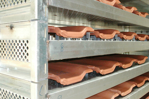
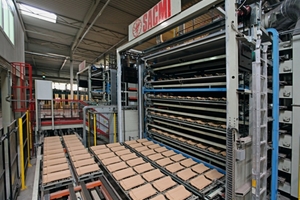
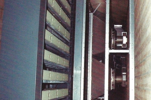
In a further step, these optimum drying conditions must be enabled for every individual tile in the dryer cross-section. To achieve this goal, a stackable drying ware support with integrated air channel and flow chicanes was designed (»Figs. 16, 18, 19). Rotho’s decision to go down this route was logical on the back of its extensive experience with the manufacture of drying support units. Feasible would also be solutions with continuously moved drying support units and stationary perforated plates [46], as preferred by SACMI (»Figs. 21, 22). However, the simple extension of the drying support units requires the smallest changes compared with conventional drying processes and can be retrofitted into these. Air is supplied into the channels from the top ends (»Fig. 18). Division of each air channel into several sections (»Figs. 16, 17) and changes in the aperture plates in the channels enable an additional, separate treatment of individual parts of the roofing tiles. For the introduction of new roofing tile models, in combination with the flexible plug-in QuickPoint supports, changes can be made to the air flow to the tiles without the need for new drying support units.
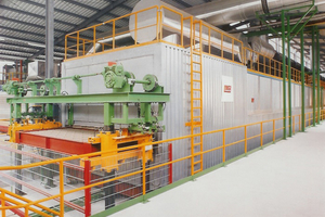
With the supply of uniformly conditioned air to every single tile on the drying support unit, all roofing tiles undergo the same treatment even in dryers with larger dimensions. Here, it is not important whether flat und accessory tiles are to be dried. The drying support units are grouped on platform cars and then go through the drying process (»Figs. 19, 20).
In »Table 6, the economic data of roofing tile dryers are listed. In contrast to dryers for masonry bricks and clinker bricks, air wall dryers for roofing tiles have clear economic advantages compared to rotary fan dryers. On the one hand, this can be attributed to the option of reversing the dryer flow. For this purpose, the running direction of the circulation fans is reversed at roughly one-hour intervals. With this measure, the drying times can be shortened by a third. Moreover, in air wall dryers for roofing tiles, with 4 to 8 m/s, much lower maximum speeds are used in the slots than in air wall dryers for masonry bricks, in which, similar to in rotary fan dryers, maximum speeds of 10 to 15 m/s are customary [50].
Accordingly, for new plants in recent decades, predominantly air wall dryers have been selected for drying roofing tiles. Even better values than the air wall dryer are shown by the high-efficiency dryer. The installation footprint is only a quarter to half the size as that for a conventional dryer. Power consumption is 60 to 70 % lower and thermal energy consumption around 20 % lower than for a conventional dryer.
The roller dryers from SACMI reach similar drying times and installation footprint to those of the high-efficiency dryer supplied by Rotho. On account of the drying support units the air must flow through and the nozzle pipes arranged at a relatively large distance above and below the tiles for impact flow, the roller dryer, however, has higher specific power consumption compared with rotary fan dryers. As for masonry and clinker bricks, rapid dryers impress with excellent economic operating data for roofing tiles. For this reason, in future for newbuild plants as well as modernizations, rapid drying processes should be preferred. With the simultaneous use of a heat pump at the rapid dryer, the energy savings between 40 and 65 % listed in »Table 1 (part 1 in ZI 5/24) are feasible. That these values are lower than the theoretical values derived from the exhaust air composition in »Table 3 (part 1 in ZI 5/24) can be attributed to the comparatively low temperatures generated with heat pumps.

![»Fig. 10: Curve of the relative drying rate as a function of the relative length l/d of a flow channel after WAGNER [41] and VOGT [50]](https://www.zi-online.info/imgs/2/1/7/3/4/8/4/tok_ae97740eef93ae46a4e8af319706398c/w300_h200_x600_y343_Bild10_Diagramm-9625639ba52720f9.jpeg)
![»Fig. 16: Cut-open drying ware supports for brick accessories with different sections in the air channel [50] (Rotho)](https://www.zi-online.info/imgs/2/1/7/3/4/8/4/tok_088e34487f246f7e8a805cc8b11b305c/w300_h200_x600_y460_Bild_16.JPG-4fb6cb4a2f735890.jpeg)
![»Fig. 17: Impact flow onto roofing tiles (Red- hot air, Blue – wet air) [47] (Rotho)](https://www.zi-online.info/imgs/2/1/7/3/4/8/4/tok_368c085ac7f34d7f406eb05d8ecca18e/w300_h200_x384_y268_Bild_17_aus_ZIarchiv-c737e4c932d1571c.jpeg)
