Internal atmosphere circulation in the tunnel kiln for energy saving in the brick firing process
1 Introduction
The total carbon dioxide emission from the German brick industry is about 1,73 million tons per year [1]. Approximately 56 % of the total emission is due to the combustion of natural gas in the tunnel kiln and dryer. The ratio of the total fuel usage in a brick factory between the tunnel kiln and dryer is 60:40. The current financial pressure faced by the industry due to the increase in the price of natural gas and the socio-political aim to become carbon neutral by 2045 increase the pressure to improve the process efficiency [2]. By 2030, the industry must reduce its carbon dioxide emissions by 36 % compared to the year 2020. That is 65 % less emissions compared to 1990 according to the new Climate Protection Law [3].
In a tunnel kiln producing bricks, the gas should flow uniformly through the brick setting. The flow resistance depends on the configuration of the setting and the porous structure of the brick. Because of this the boundary of the setting will be heated or cooled with respect to the center of the setting. To achieve a uniform heating of the setting in the preheating zone, some tunnel kilns are equipped with burners [4] or have a long firing zone. In the firing zone, the required turbulence for the temperature homogenization in the vertical direction is achieved by high exhaust impulse and frequency control of the burners [5]. To increase energy efficiency, the gas from the firing zone should transfer its enthalpy to the setting in the preheating zone. In the cooling zone, there are many cooling air injections at the end cooling zone and rapid cooling zone along with the air extractions at the beginning and end of the static cooling zone. These injections and extractions create a homogeneous vertical temperature distribution of the air in the cooling zone leading to a uniform setting temperature in the vertical direction.
The heat transfer between the ware and the gas in the tunnel kiln is due to convection and radiation. The proportion of convection is up to 80 % [6]. Because of the high influence of convection on the heat transfer, the circulation system can be considered as an alternative to the burners in the preheating zone, to attain homogeneous temperature of the setting thereby reducing the fuel requirement of the tunnel kiln. External circulation systems have contributed to developing uniform temperature in the ware. Therefore, an experimental study on the influence of a circulation system on the firing of different kinds of brick and the temperature homogenization of the gas atmosphere were carried out at the Brick and Tile Research Institute Essen (IZF).
2 Experimental Setup
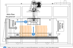
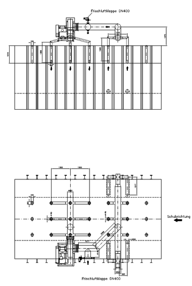
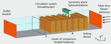
The existing experimental furnace is side-fired and has a clear height of 1.70 m, a width of 3.5 m, and a length of 4 m. Thus, it has a free volume of 23.8 m³. The furnace has 6 natural gas burners and each has a power of 65 kW. The special feature of this chamber furnace is that it has a longitudinal circulation and thus has a longitudinal flow as it exists in the tunnel kiln, and therefore represents a segment of a real tunnel kiln as seen in » Figure 1. On the inside of the furnace, on the ceiling, the internal circulation system was installed and put into operation. The housing and impeller of the internal circulation system are metallic. Thus the internal circulation system can be operated safely up to a max. temperature of approx. 550 °C, without any damage due to creep deformation. The internal circulation system extracts the gas from the middle of the setting and forces air to the inlet direction. The outlet direction of the gas from the internal circulation system is opposite to the main flow through the inlet as seen in » Figure 1. The volume flowrate extracted by the internal circulation system is adjusted by the rotational speed of the fan and the rotational speed of the fan was changed in steps of 5 Hz from 10 Hz to 50 Hz.
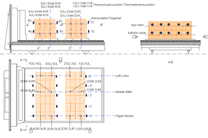
Anemometers are used to measure the velocity of the gas throughout the setting and are located at 15 different locations in the chamber as shown in » Figure 2. The anemometers which measure the velocity of the gas at the front, center and back of the setting are designated as 4, 3 and 1 respectively. At the front of the setting, velocity is measured at the top and bottom of the setting which are designated as 4O and 4U respectively and have 5 anemometers on top and bottom each. The velocity at the center and back of the setting is also measured by anemometers which are distributed similarly to the front of the setting. Thermocouples are used to determine the temperature of the bricks at different positions in the setting and the temperature of the gas in the chamber. Four different cross section planes in the setting which are numbered as 4 ,3, 2, and 1 from the inlet side are used to study the temperature homogeneity in the cross section of the setting. At each cross section, for example at cross section 4, 3 thermocouples are located at the top and 3 thermocouples are located at the bottom. At the top of the cross section 4, the 3 thermocouples measure the temperature at the left, middle and right side and are designated as 4OL, 4OM and 4OR respectively. At the bottom of the cross section 4, the 3 thermocouples measure the temperature at the left, middle and right side and are designated as 4UL, 4UM and 4UR respectively. The cross sections 3, 2 and 1 have 6 thermocouples each. In total, there are 24 thermocouples measuring the temperature of the brick setting and 3 thermocouples measure the temperature of the gas (5, 6 and 7).
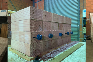
The different kinds of bricks selected for the experiment are MZ70, W10 and clinker. The most important distinguishing feature of MZ70 and W10 are the hole structures and thus the open, free-flowing surface area to flow through. The total hole cross-section of the MZ70 is approximately 64 %, that of the W10 is 54 %. The decisive factor for the flow is the pressure drop across the flow cross section. In the case of the MZ70, this is considerably lower due to the larger open structures than the filigree hole pattern of the W10. » Figure 3 shows the arrangement of the MZ70, W10 and clinker on the kiln car of the experimental setup. For the MZ70 and W10, there are 2 setting packs with 96 bricks each on the kiln car. This means with a brick weight of 12 kg (MZ70) and 15 kg (W10), the weight of brick on the kiln car is 2,300 kg and 2,800 kg, respectively. For the clinker, 2 setting packs with 10 pillars each, with 80 bricks each is placed on the kiln car and the total weight is 5400 kg with each clinker weighing at 3.4 kg.
For each of the settings, experiments were conducted with and without the firing of the burners for rotational speeds of the internal circulation fan at 30 Hz and 50 Hz. The experiments without the firing of the burners are used to understand the velocity distribution of the air in the setting with and without an internal circulation fan. The experiments with the firing of the burners are used to understand the temperature homogenization of the setting when the internal circulation fan is operated.
3 Results and Discussions
3.1 Experiment without burners in operation
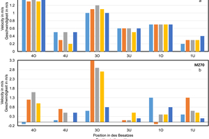
» Figure 4a shows the velocities recorded by each of the 5 anemometers at the different positions in the setting without circulation system and » Figure 4b shows the relative change in the velocity when the circulation system is operated at 30 Hz compared to the case without ventilator. From » Figure 4a, the velocity values of the anemometers located at the top position at the front (4O) are almost the same and also almost twice of those recorded at the bottom (4U). As can be seen from » Figure 1, the sharp bend at the bottom after the inlet will inhibit the flow through the anemometers at the bottom section at this position (4U). The velocities measured by the anemometers at the top at the middle (3O) are also almost the same but less than that measured at 4O. The velocities measured at 3U are higher than those at 4U which means that the highly porous MZ70 allows the air to flow through rather than obstruct it. At the back of the setting, the velocities measured by the anemometers at the top (1O) and bottom (1U) are about 50 % and 25 % less than those measured at the top (4O) and bottom (4U) position of the setting’s front respectively. This shows that the flow of gas through the setting decreases by 50 % in the kiln chamber of length 3,5 m which directly influences the heat transfer from and to the ware. When the circulation system is operated with a frequency of 30 Hz, the air is sucked by the circulation system located at the middle of the chamber kiln leading to an increase in the flow of air through the center of the setting. This can be seen by the high relative increase in the velocities recorded by the anemometer 3 and 4 at different positions (» Figure 4b). The negative values as seen in » Figure 4b mean that the velocity at these positions are reduced compared to the case without circulation system. The velocities at the top of the middle position (3O) in » Figure 4b are higher as compared to the velocities at the bottom of the same pillar (3U) which can be attributed to the operation of the circulation system at this location. Flow of air through top (1O) and bottom (1U) positon at the back increases uniformly in the case with circulation system.
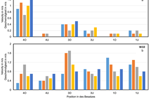
The velocity values recorded by the anemometer at various position in the setting of W10 bricks without circulation system and the change in the velocity values with circulation system operated at 30 Hz are depicted in » Figure 5a and » Figure 5b respectively. As seen in » Figure 5a, the flow through the brick is uniform in the top (4O) at the front of the setting and minimal at the bottom (4U). The flow velocity through the brick at the top in the middle (3O) and in the back (1O) decreases by more than 50 % and 80 % respectively. Because of the high number of small sized holes in the bricks, the flow is blocked and will pass through the top wall gap and side gaps rather than through the setting which will reduce the velocity through the holes in the brick and hence the heat transfer coefficient. When the circulation system is operated at a frequency of 30 Hz, the suction of the air at the top center of the chamber causes the flow of air to be concentrated along the center of the setting and not through the gaps between the top and walls of the chamber. As seen in » Figure 5b, there is an equal increase in the velocity values recorded by the anemometers compared to the case without circulation system. The main point is that the velocity of air through the top (1O) and bottom (1U) at the back increases by an average value of 1m/s for both positons.
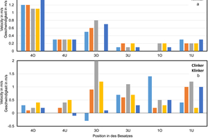
The velocity of the air at different positions in the setting of clinker and the change in the velocity of air with circulation system at a frequency of 30 Hz compared to without circulation system are shown in » Figure 6a and » Figure 6b respectively. The velocity of the air through the clinker setting decreases as seen in » Figure 6a by more than 85 %. With the use of circulation system, the flow velocity increases at the back of the setting which is the exit of the chamber kiln as depicted in » Figure 6b.
When the circulation system frequency was increased to 50 Hz, the increase in the velocities at different positions in the setting was similar to the case with circulation frequency of 30 Hz for all the different kinds of brick format (MZ70, W10 and clinker).
3.2 Experiments with burners in operation
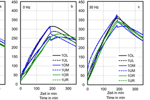
» Figure 7 shows the temperature development in the MZ70 setting. » Figure 7a shows that the temperature increases at the cross section 4 when the circulation system is not in operation. Since at the entrance of the chamber, the distribution of the flow is uniform as seen in the velocity diagram » Figure 4a, the temperature at the cross section 4 is uniform. Because of the uniform distribution of gas at the inlet, the temperature of the setting at cross section 4 is almost homogeneous without circulation system and with circulation system. » Figure 7b shows the temperature distribution of the setting at the cross section 1 and that temperature development at the top right (1OR) and top middle (1OM) lags behind the other positions. The other positions have a temperature difference of 50 K after 100 min like at the cross section 4 (» Figure 7a). This shows that for MZ70, the gas flows through the setting in a homogenous manner which is also clearly understandable from the uniform velocity through the setting at the back as seen in » Figure 4a (1O). When the circulation system is in operation with a rotational speed of 30 Hz, the temperature difference in the setting at the cross section 1 at 100 min is almost 100 K as depicted in » Figure 7c. The temperature at the top middle (1OM) and top right (1OR) are increased from less than 200 °C to more than 250 °C. When the rotational speed of the circulation system is increased to 50 Hz, the temperature difference in the setting at the cross section 1 is reduced to 50 K from 200 K after 100 min as seen in » Figure 7d.
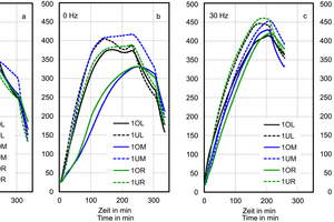
» Figure 8 shows the temperature development in the W10 setting, mainly in the setting at the cross sections 4 and 1, when no circulation system is used and when the circulation system is operated with rotational speeds of 30 Hz and 50 Hz. The increase in the temperature of the setting at the cross section 4 is uniform as seen in » Figure 8a. At the end of the kiln (1), » Figure 8b, a high temperature gradient of approx. 200 K is also established after 100 minutes without a circulation system, whereby a greater difference is recorded at the various positions in the setting compared to the MZ70. The temperature distribution in the setting at the cross section 1 is non homogeneous as seen in Figure 8b which is due to the restriction of the flow of the gas thorough the W10 setting. The restriction of the flow of the gas in the setting at the back can also be clearly seen from the » Figure 5a where the velocity of the gas is less through the back of the setting (1O and 1U) compared to the front of the setting (4O and 4U). When the circulation system is used with a rotational speed of 30 Hz ( » Figure 8c), the temperature difference in the setting at the cross section 1 is almost 100 K after 100 minutes which is reduced from 175 K without circulation system. After 100 minutes, the highest temperature in the setting increased from 225 °C without circulation system to 375 °C with circulation system operating at a rotational speed of 30 Hz. When the rotational speed is increased to 50 Hz (» Figure 8d), the temperature difference in the setting at the end (1st positon) at 100 minutes does not change as compared to the rotational speed of 30 Hz.
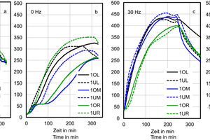
» Figure 9 shows the temperature development in the clinker setting. The temperature difference in the setting at the cross section 4 is almost 75 K after 100 minutes as shown in » Figure 9a. Whereas at the cross section 1, the temperature difference after 100 minutes is almost 100 K as seen in » Figure 9b. When the circulation system is operated with a rotational speed of 30 Hz (» Figure 9c), the temperature difference at 100 minutes decreases to 75 K and the lowest temperature of the setting increases to 200 °C compared to the 125 °C without circulation system (» Figure 9b). This is due to the increase in the flow of the gas through the setting at the cross section 1, which was created due to the circulation system as can be seen in the » Figure 6b. When the rotational speed of the circulation system is increased to 50 Hz (» Figure 9d), the lowest temperature at the cross section 1 after 100 minutes is 200 °C which is almost the same as when the rotational speed is 30 Hz. Except for the lower middle position with a high temperature (1UM in » Figure 9d), the temperature difference in the setting is almost 75 K after 100 minutes which is similar to the case with rotational speed of 30 Hz (» Figure 9c). The same temperature difference and the same lowest temperature in the setting at the cross section 1 when the rotational speed is increased from 30 Hz to 50 Hz show that the thermal conductivity is a predominant factor for the heat transfer, even when the convective heat transfer is increased.
4 Conclusions
The internal circulation system is shown to have increased the distribution of the gas in all the three brick setting with the brick type MZ70, W10, and clinker. A significant improvement in the velocity of the gas through the setting of W10 and clinker was observed when the internal circulation system was in operation. The improvement in the velocity of the gas in the setting increased the temperature homogeneity across the cross section of the setting, which leads to the reduction in energy requirement. The advantage of internal recirculation is that it can be used directly in the kiln chamber, eliminating the need for complex pipework. The disadvantage of retrofitting is that the kiln ceiling would have to be retracted or the setting height on the kiln car to be reduced. In the latter case, additional guiding devices must be installed in the kiln to avoid the flow of gases through the top gap of the setting. In the case of a new kiln, the corresponding plans are easier and more efficient to implement. The length of the preheating zone could be reduced in this way, but is limited by the low thermal conductivity of the brick products. Thus the utilization of the enthalpy of the kiln atmosphere with the aid of internal circulation system increases the thermal efficiency of the kiln and achieves a high product quality because of the improved temperature homogenization of the ware.
Acknowledgement
This research project, IGF-Project No. 21010 BG, was funded by the German Federal Ministry of Economic Affairs and Climate Protection through the Industrial Research Association “Otto von Guericke” (AiF) and supported by the Research Foundation “Brick and Tile”.

