Mass flow controllers for different automation concepts
Gas supply and furnace atmosphere safely under control
For precise control of the gas atmosphere in hardening furnaces, the use of mass flow controllers (MFC) is state of the art. However, such heat treatment plants are very differently constructed and have different requirements for the gas supply. The components used must therefore be adapted to the situation on site. This also requires that the mass flow controllers fit into the respective automation concepts.
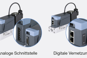
Mass flow meters do not work autonomously when controlling the furnace atmosphere, because the required gas quantities have to be adjusted again and again. How the MFCs are to be integrated into the respective plant for this purpose can differ considerably (Fig. 1). The possibilities range from data exchange via the „classic“ analogue interfaces and digital networking with all common fieldbus protocols to plug-and-play-capable MFC assemblies or complete control cabinets that contain all components for controlling the furnace atmosphere.
Analogue interface: the classic for simple applications
For smaller or simpler heat treatment systems where only a few data are to be transmitted, the classic analogue interface can still be a good choice. The common 4...20 mA or 0...10 V signals are usually used, and more rarely 0...5 V or 0...20 mA signals. Commissioning and maintenance are uncomplicated and the signals can be tested with simple tools. The analogue devices are very easy to exchange, regardless of the manufacturer, because these signals are independent of the respective control system.
Only the actual value and setpoint of the control system are transmitted via the analogue interface, plus possibly a fault message as a binary signal. Since the introduction of internally digital electronics, MFCs with analogue interfaces also provide much more information internally, which can be read out manually via the service interface that is usually available. However, this is a solution for maintenance or commissioning and not for ongoing operation.
Digital interface: Modern supplier of diagnostic data
If, in addition to setpoint and actual values, diagnostic data are also to be automatically transmitted to a higher-level control system, the mass flow controllers must communicate via digital interfaces, e.g. PROFINET, EtherNet/IP, PROFIBUS DP, Modbus TCP, EtherCAT, CANopen or RS485. Which bus is actually used depends on the requirements of the entire system. The susceptibility to interference, the costs of the components, the distribution of the bus, the availability of devices with this interface and safety aspects all play a role in the selection.
In principle, any information that is available internally can be transmitted via the digital interfaces. In practice, however, one usually limits oneself here in order not to let the transmitted amount of data per cycle become too large and to limit the load on the bus by individual participants. In addition to the process data, only the frequently required information is transmitted cyclically, i. e. in each transmission cycle and several times per second. The typical information include above all the medium and unit temperature as well as status messages of the unit‘s internal diagnostics, for example hardware errors, but also other operating states such as manual mode, autotune or the detection of limit values. In addition, there is often further-reaching information, such as the degree of actuation of actuators, i. e. how far a valve is opened in relation to the desired flow rate, for example.
Less used values are either transmitted less frequently or acyclically when the higher-level control system requests them. These include, for example, variations in the control parameters, a switchover of the gas characteristic curve or user-specific values. But calibration and setting data of the MFC can also be read out and visualised in this way.
Basis for documentation, diagnosis and calculation
Digital interfaces thus open up a lot of potential. For example, by reading out and saving continuous system data, the documentation obligation vis-à-vis quality assurance and the client is automatically possible, especially since the respective device can also be clearly identified by its device and serial number. This guarantees traceability.
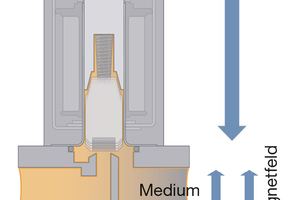
The possibilities that lie dormant in the data provided by the digital interfaces are also the basis for today‘s current Industry 4.0 concepts. However, caution is called for here: Considered on its own, this information is by no means sufficient for this. Since the MFC only „knows“, for example, how far it has to open its actuator for the required flow, this information alone is not yet meaningful enough for an in-depth analysis of the state of the entire gas supply. A change in the control of the valve can indicate very different causes (Fig. 2). The inlet pressure may be reduced because the gas cylinder is empty. However, the outlet pressure may also have increased, which would only be noticeable at high flow rates. If the values are lower than usual only at high flow, the inlet filter may be clogged or there may be other problems in the supply line. A clearly increased temperature at the control valve is also a possible culprit. In order to draw further conclusions about the condition of the entire system from the changes in the output level of a valve, further information is needed, for example, messages from pressure or temperature sensors or level values from storage tanks. The exact analysis remains with the operator.
If the volume counters at the beginning and end of a batch process are read out via the digital interface of an MFC, it is possible to record the consumption of a batch or a specific process step. This makes it possible to produce a very accurate calculation or invoice to the customer. In addition, the total consumption can also allow conclusions to be drawn about the condition of the oven such as its tightness or the condition of the treated products, for example their reactivity, the absorption of certain gases or the surface structure.
Subordinate networks for extensive furnace systems
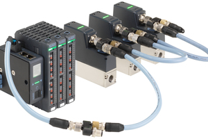
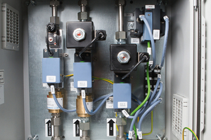
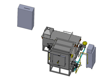
In some cases, one also finds multi-level bus systems with a very fast, complex bus for communication between parts of the plant and a simpler bus for communication at the lowest level. Digitally controlled MFCs can then be combined in such a sub-network (Fig. 3). MFCs with „simpler“ interfaces are less expensive than those with a „high-end“ interface; moreover, the typical amount of data that needs to be exchanged is relatively small. Such a sub-network is connected to the higher-level network via a gateway. In this way, local assemblies can be created at low cost, which are constructed and installed as small „gas rule“ switch cabinets or manifolds. These can be standardised and used as plug-and-play „assemblies“ in larger systems. In principle, the cabinets can always be the same, but they can also be project-specific and individually adapted to the application (Fig. 4).
These self-contained systems are then connected to the plant‘s higher-level PLC via an Ethernet connection point, for example. They can also have their own logic, so that adaptation to changed processes is possible without additional intervention in the furnace control system. Within this self-sufficient „black box“, design optimisations and further developments are possible at any time without having to intervene in the actual furnace design. In addition, the control cabinets offer the installed components protection against environmental influences, mechanical damage and unauthorised intervention.

